View or comment on this project log on Hackaday.io
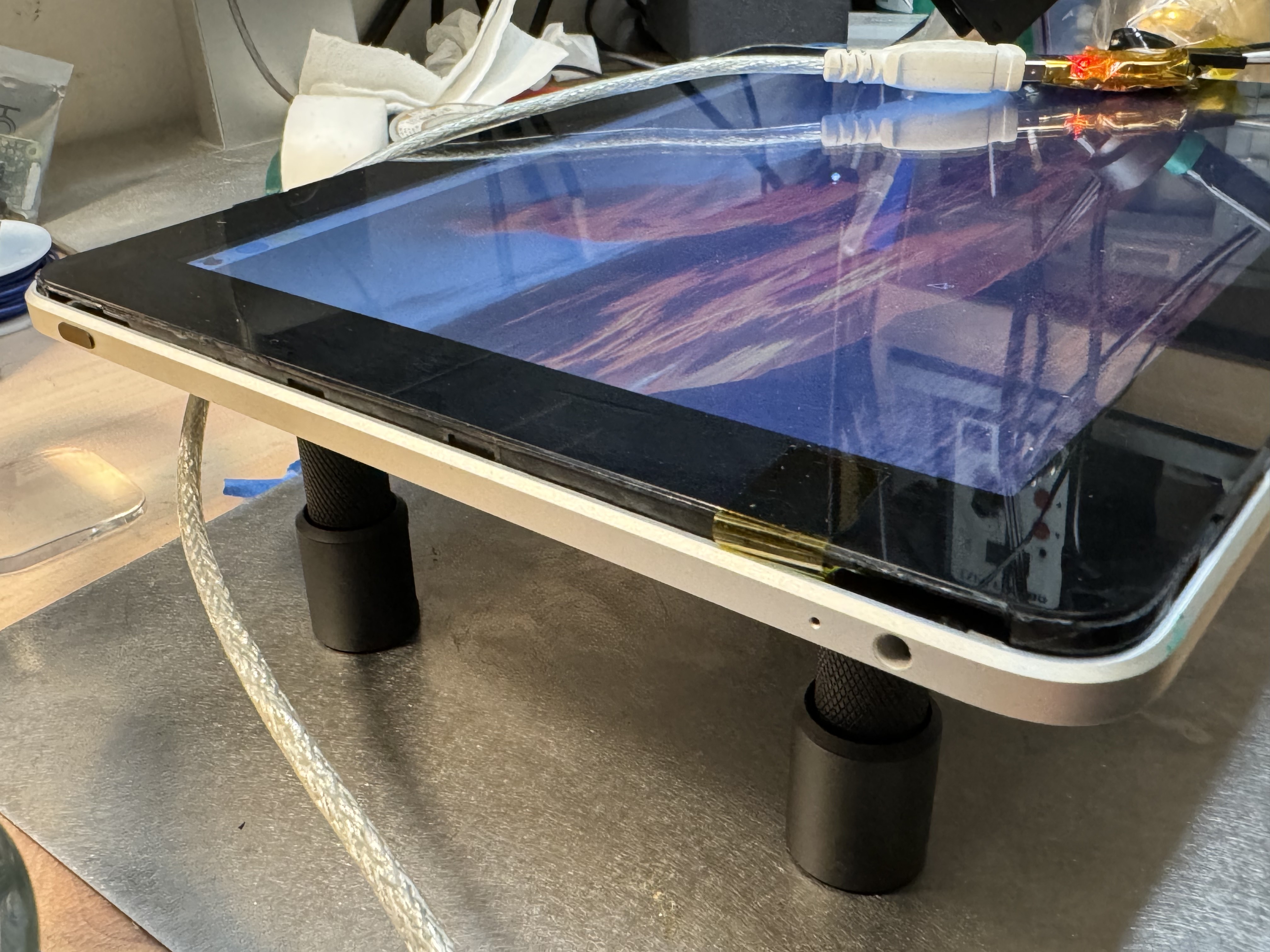
It works!
I ordered the second revision of my PCB a few months back, and have been slowly working my way through testing and debugging the functionality. So far, the PCB hasn't required any modifications -- all the issues I've encountered have been soldering or software issues.
A brief list of things I tested / debugged:
- PCIe port (for the NVMe drive) worked without issue.
- 5V boost converter mysteriously stopped working -- the 787k resistor turned into a 150k resistor?? Maybe I just placed the wrong resistor there in the first place, but I swear this was working before. (I use a 787k and 150k resistor as a feedback network for the MP3422GG boost converter.) Replacing the resistor fixed the issue.
- Battery charger wasn't charging, until I discovered some passives were missing. Replacing them fixed the issue.
- LCD backlight controller wasn't working, until I noticed that the inductor had a bad solder joint. Touching that up with a soldering iron fixed the issue.
- The image on the LCD was corrupted -- at first, it was showing 3-ish copies of the screen vertically, like it was skipping all but every 3rd line. After messing with timings and frequencies for a while, I noticed that pressure on the board would change the severity of the problem (see youtube video below). At some point, the problem got significantly better, where the screen would be relatively stable vertically, but individual lines would be corrupted at some point. (Unfortunately, forgot to get a photo of this.) I noticed that it would improve when I cranked up the LVDS differential output voltage on the sn65dsi83 (CHA_LVDS_VOD_SWING in the datasheet). This indicated to me that there was an analog problem on the board. Hitting the sn65 and the LVDS connector with some flux and hot air solved the issue.
- A while later, I noticed that my battery voltage was really low, and that it wasn't pulling any current from the USB power supply. After looking for any error codes or anything weird in the i2c registers of the battery charger IC, I bodged an LED and resistor onto the STAT pin of my charger IC, and that glowed solid. If there were a fault code, it would've blinked at 1Hz. Once again, flux and hot air solved the issue.
- I tested the touchscreen - clean (none of the noise that plagued my earlier board revision; dunno why this is any better, as the only change I made to this part of the hardware was rounding the tracks to look pretty), but had a dead zone on the middle few Y lines. More flux and hot air fixed that.
I'm beginning to think that my bismuth-based low temperature solder is a bad idea, especially since the 0.8mm PCB is so flexible.
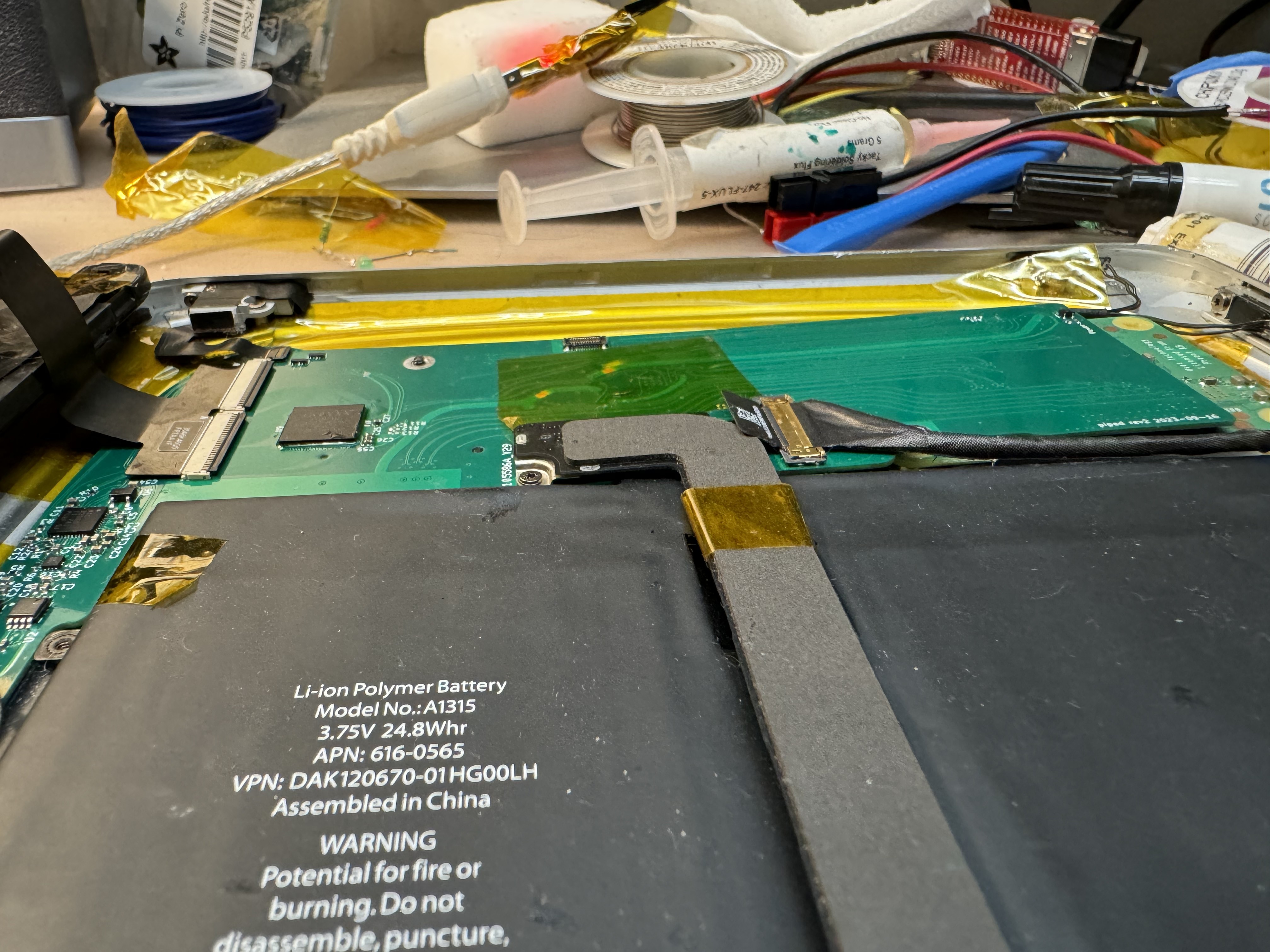
Anyway, with all those issues worked through, I decided to assemble the whole thing into tablet form (removing the battery wires I had soldered into place for testing purposes) and take a little victory lap.
Next steps
There's still a few more bits of hardware to test:
- The soundcard (this is probably the next thing on the agenda)
- SDIO communication with the battery
- At some point I really need to see if I can talk to the ambient light sensor + compass; I've been wiring up that connector on every board rev and never done anything with it.
- I think/hope the compass has an accelerometer as well, which would let me automatically change the screen orientation as I rotate the tablet.
There's also a bunch of stuff I'd like to do with the dock connector:
- See if I can support USB peripherals through the "Camera connector" dongle
- Support the iPad Keyboard Dock
- Test component video output
- I'd really like to get the iPad's own Wifi/BT radio working (this is actually mounted on the PCB that connects the logic board to the dock connector.)
Also, Raspberry Pi OS's GUI is barely functional on a tablet:
- You can pull up an on-screen keyboard through the menu, but it only supports letters, space, enter, and backspace? No numbers, symbols, modifier keys (it can type uppercase letters though), autocorrect, etc.
- The on-screen keyboard doesn't appear automatically.
- The UI is clearly meant for a mouse; all the buttons are too small to be effective tap targets.
I'd like to play around with Ubuntu Touch / UBPorts and/or Android. These should provide a much more usable interface.
Some other software improvements to make:
- Make sure the battery status (percentage, charging/discharging) shows up in the UI
- Get the volume buttons, orientation lock, and home button (front button) working.
- Convince the OS to hibernate instead of shut down when I press the lock button. Maybe if you press the button for >2s, have it pull up a power menu?
Finally, I'll probably need to do another board revision to get the case to close entirely:

I might end up having to make parts of the board out of flex PCB. Basically, the CM4 and its connectors make the board about as thick as it can be and still fit in the case, but the CM4 is on the bottom, and I need some parts on top of the board fairly close to the CM4. If the board were flexible, this might just work.
